![]()
April 29, 2026
![]()
April 29, 2026
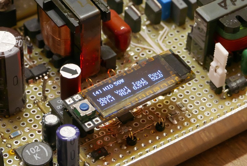
There are some methods to know that the operating condition of embedded control program in the working systems. If the system has a graphic display, a debug mode will be implemented to the program so that it can output the debug information on the display. However, not all embedded systems have a rich display device, and instead, some system have a debug and maintenance task controlled via a UART.
I often need to monitor the UART output on the board temporarily. If the output is not so much and limited number of values, I do not want to bring the PC but want to monitor it in easier way. For shch case, a simple display module with serial input will be useful, so that I built a tiny plug-in serial display module for program/debug port on the board.
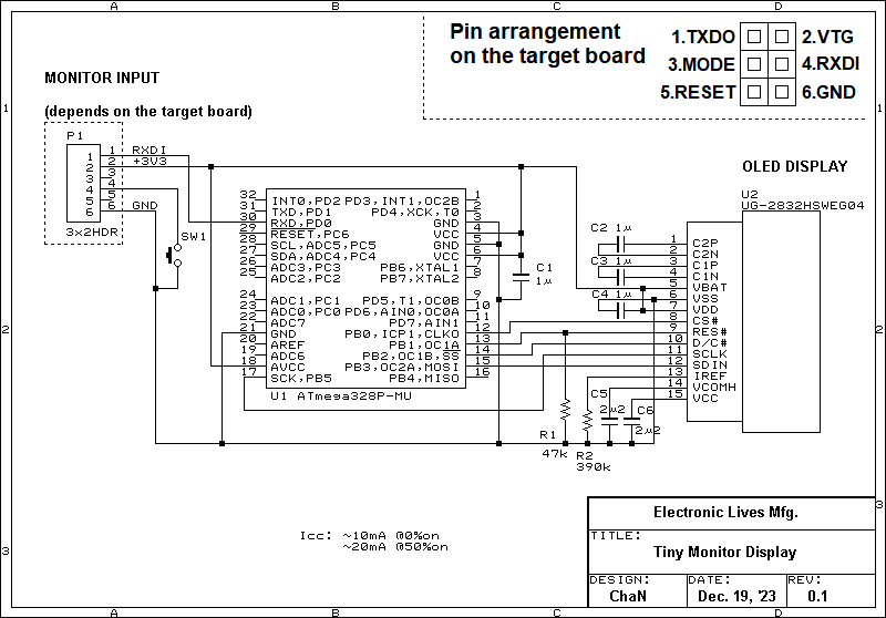
Right image shows the schematic of built serial display module. A tiny 128x32-dot OLED module is used for the display and it is controlled by an MCU, ATmega328P from Microcnip. The display module is intended to be pluged directly on the on-board program/debug connector, so that the connector type and pin arrangement will need to be matched with the target board. I use the pin arrangement in the schematic for the most project. The SW1 is a simple command input method that to use the RXDI line for not only UART but also GPIO. The target board needs to consider that the display module pulls 10-20 mA from VTG pin. If the supply voltage on the VTG is higher than 3.3 V, a voltage regulator and a logic level converter need to be placed on the module.
The received data from the target board is displayed into the OLED display module in simple TTY protocol. When the font size is in 6x8, it can display in 21 columns by 4 lines into 128x32-dot OLED display. I have not intended to control the output it in rich protocol, so that only some control characters, \r, \n and \f are implemented. In addition, an ANSI cursor positioning command, \e [ r ; c H, can also be added by a build option.
